Imagine spending months building a beautiful model railway, carefully installing the tracks, creating realistic scenery, and wiring every turnout. Everything works perfectly in your workshop.
Then you transport the layout to an exhibition, connect the modules, and suddenly discover that the tracks don’t line up.
Frustrating, right?
This is exactly why advanced baseboard engineering matters so much in modular railway modelling.
A successful modular layout needs more than attractive scenery and reliable locomotives. It requires a strong, lightweight, precisely constructed foundation that can survive repeated assembly, transportation, and environmental changes.
Unlike permanent railway layouts, modular systems must maintain accurate track alignment even after being dismantled and rebuilt dozens of times.
That’s where thoughtful structural engineering makes a huge difference.
Advanced baseboard engineering for modular model railway systems combines material selection, precision woodworking, mechanical connections, electrical planning, and practical transport considerations.
Whether you’re building an OO gauge exhibition layout, an N gauge railway network, or a collaborative modular system, understanding these techniques can save considerable time and frustration.
Let’s explore how to build railway baseboards that remain stable, portable, and dependable for years.
1. Understanding the Engineering Requirements of Modular Baseboards
A modular railway baseboard is much more than a wooden platform supporting miniature tracks.
It’s a structural component that must maintain its shape while supporting trackwork, scenery, electrical equipment, and occasionally substantial loads from operators handling the layout.
Unlike a permanent installation, modular systems experience repeated movement, assembly, and disassembly.
Structural Stability Versus Portability
The biggest engineering challenge is balancing strength with weight.
A heavy baseboard might feel extremely sturdy, but transporting several large modules quickly becomes exhausting.
On the other hand, an excessively lightweight structure can twist, sag, or become damaged during handling.
The ideal construction provides high stiffness without unnecessary material.
This is why modern modular railway builders increasingly favour reinforced plywood frameworks, open-grid structures, and lightweight torsion-box designs.
These methods distribute loads effectively while keeping the overall structure manageable.
Establishing Design Requirements
Before choosing materials, determine how the modules will actually be used.
A layout permanently installed in a spare bedroom has different requirements from one that travels to exhibitions several times a year.
Consider the available storage space, transport vehicle dimensions, module weight, operating height, and number of people available for assembly.
For example, a 1,200 mm module might fit comfortably in a workshop but become awkward when carried through narrow doorways.
Modular engineering begins with understanding these practical restrictions rather than simply cutting plywood into convenient rectangles.
2. Choosing the Right Baseboard Construction Method
Several structural approaches work well for railway modelling.
The best choice depends on module dimensions, track arrangements, weight restrictions, and available construction tools.
Traditional Open-Grid Baseboards
Open-grid construction uses a rectangular framework reinforced by crossmembers.
A plywood track surface is then attached to the supporting structure.
This method is relatively straightforward and provides good access to wiring, point motors, and other equipment beneath the layout.
The National Model Railroad Association describes open-grid benchwork as a practical approach using regularly spaced framing members.
However, modular builders should pay particular attention to joint strength and dimensional accuracy.
A poorly assembled rectangular frame can gradually become distorted through repeated handling.
Torsion-Box Construction
Torsion-box engineering offers an attractive alternative for advanced modular layouts.
Instead of relying on a simple frame, the structure uses upper and lower skins connected by internal ribs.
When properly bonded together, these components form a stiff assembly that resists bending and twisting.
The principle is similar to lightweight structural panels used in furniture and other engineered applications.
For a model railway, a torsion-box design can provide excellent stiffness without requiring thick, heavy timber throughout the structure.
However, internal reinforcement must be positioned carefully to leave space for electrical wiring and mechanical equipment.
The Speed-Mo modular railway standard provides an example of lightweight plywood torsion-box construction.
L-Girder and Hybrid Frameworks
L-girder construction uses structural members arranged into L-shaped beams.
These support crossmembers and trackbed sections, allowing considerable flexibility during layout development.
It’s particularly useful when creating different terrain elevations.
For transportable modular systems, a hybrid design may be more practical.
A rigid perimeter frame can be combined with lightweight internal supports and removable scenery sections.
This approach provides a balance between structural performance and flexibility.
3. Selecting Materials for Strong and Lightweight Railway Modules
Material selection directly affects the weight, durability, and long-term stability of a modular baseboard.
Not all plywood, timber, or engineered panels behave the same way.
Understanding their characteristics helps prevent expensive construction mistakes.
Birch Plywood and Engineered Timber
Good-quality birch plywood is popular because its cross-laminated construction offers relatively consistent strength and dimensional stability.
Compared with some inexpensive sheet materials, high-quality plywood generally provides better screw retention and resistance to structural damage.
For an illustrative lightweight module, builders might use 9–12 mm plywood for selected framing components, with additional reinforcement where necessary.
These dimensions are examples rather than universal engineering requirements.
The correct thickness depends on span length, internal bracing, expected loads, and the particular plywood grade.
Thinner materials may work effectively in torsion-box construction because structural stiffness comes from the complete assembly rather than one individual sheet.
MDF, Foam, and Aluminium
Medium-density fibreboard offers a smooth surface and consistent thickness.
However, it can be relatively heavy and vulnerable to moisture-related swelling, particularly at exposed edges.
For frequently transported modules, plywood is often more forgiving.
Rigid insulation foam is excellent for landscape construction and reducing scenery weight.
Nevertheless, foam usually requires an appropriate supporting structure when used in modular layouts.
Aluminium framing can also be an effective choice, particularly for precision-built exhibition systems.
Its advantages include dimensional consistency, corrosion resistance, and potentially lightweight construction.
However, aluminium components may require specialised fittings, drilling techniques, and careful consideration of thermal expansion.
Protecting Materials Against Moisture
Wood-based materials respond to changes in temperature and humidity.
Unprotected panels can absorb moisture unevenly, leading to swelling, movement, or distortion.
Seal exposed surfaces, including undersides, internal faces, and end panels, using suitable finishes.
This doesn’t make timber completely immune to environmental changes, but it helps reduce moisture-related problems.
Allow materials to acclimatise before final assembly whenever possible.
4. Engineering Precision Connections Between Modules
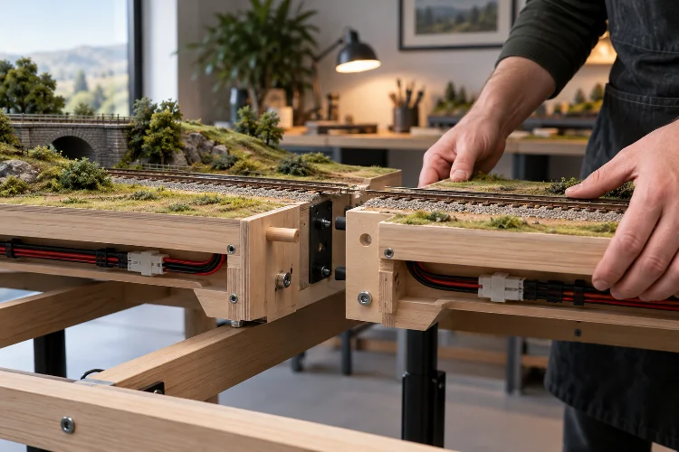
The connection between neighbouring baseboards is one of the most critical areas of modular railway construction.
Even a strong, well-built module can become unreliable if its joining system allows movement.
Mechanical alignment must be repeatable, secure, and easy to reproduce.
Using Alignment Dowels
Precision alignment dowels help neighbouring modules return to the same relative position.
Metal dowels and matching bushes are commonly used in custom modular baseboard systems.
They can provide accurate horizontal and vertical positioning when installed correctly.
However, alignment dowels should not be expected to carry every structural load.
Bolts, clamps, or suitable fastening hardware should secure the modules together.
The dowels establish their relative position, while the fasteners maintain a dependable connection.
Bolts and Mechanical Fasteners
Through-bolts with washers and suitable nuts are widely used in modular railway systems.
They provide reliable clamping and allow damaged hardware to be replaced.
For custom baseboards, M6 or M8 bolts may be appropriate depending on the connection design.
The correct size should be chosen according to the module’s construction and loading requirements.
Avoid placing fasteners so close to the edges that the surrounding material becomes weak.
Reinforcing the end plates can help distribute clamping pressure.
Learning From Free-mo and FREMO Standards
Established modular standards demonstrate the importance of interface compatibility.
For example, the NMRA British Region’s HO Free-mo specification defines particular module-end dimensions, track positions, and connection requirements.
Its single-track interface uses an 18-inch-wide end plate with the track centred.
FREMO’s N-RE system uses different interface arrangements and defines the positions of connection holes relative to the track centre.
These systems aren’t interchangeable by default.
The important lesson is that modules intended to connect must follow the same agreed interface standard.
For a private OO gauge railway, you can establish your own dimensions, but document them carefully before constructing additional boards.
5. Maintaining Accurate Track Alignment Across Baseboard Joints
Track alignment is where mechanical engineering becomes directly visible during railway operations.
Even slight differences in rail height or horizontal positioning can cause locomotives and rolling stock to derail.
Precise track installation is therefore essential.
Preparing the Module Ends
End plates should be flat, square, and firmly attached to the surrounding framework.
The trackbed must remain accurately positioned relative to these ends.
Use a straightedge, engineer’s square, and suitable measuring tools to check the assembly.
Don’t rely on visual judgement alone.
Small measurments errors can become more significant when several modules are connected.
A mistake repeated across multiple joints can create noticeable changes in track alignment.
Securing Rails at Module Boundaries
Rails near module boundaries require firm support.
One established technique involves soldering rail ends to copper-clad sleepers securely attached to the baseboard.
Another method uses appropriately positioned brass screws as rail anchors.
These supports help prevent the rails from moving during transportation.
When using copper-clad sleepers, ensure the copper is electrically isolated between rails where necessary.
Rail ends must also be finished neatly to avoid wheel impacts at joints.
Avoiding Awkward Track Geometry
Where possible, arrange tracks to cross module boundaries at right angles.
This simplifies alignment and reduces unexpected directional changes.
Some modular standards also require straight track for a defined distance before each interface.
For example, the HO Free-mo specification requires six inches of straight track approaching a modular end.
This helps prevent sharp reverse curves when different modules are connected.
For custom systems, establish a similar principle appropriate to your chosen scale and rolling stock.
6. Designing Adjustable and Stable Module Support Systems
Strong baseboards still need dependable support.
Poorly designed legs can make even a rigid structure unstable, particularly on uneven exhibition floors.
The support system should provide vertical adjustment without allowing excessive lateral movement.
Adjustable Legs and Levelling Feet
Adjustable feet are particularly useful because floors are rarely perfectly level.
FREMO’s N-RE guidance specifies leg adjustment of at least ±20 mm, with ±30 mm preferred.
That amount of movement can help compensate for variations in floor height.
The same guidance commonly uses a rail-head height of approximately 1,300 mm for its N-RE modules.
Other modular systems specify different heights.
Always follow your selected interface standard rather than assuming that one exhibition height works for every group.
Preventing Sway and Structural Movement
Tall, unsupported legs can allow a layout to wobble.
Cross-bracing or rigid paired-leg assemblies help resist sideways movement.
Removable legs can make transportation easier, but their attachment points must remain secure.
Avoid relying on neighbouring modules to compensate for unstable supports.
A modular layout should distribute loads predictably across its supporting structure.
Where practical, test individual modules for stability before connecting them into a larger arrangement.
7. Planning Electrical Wiring During Baseboard Construction
Electrical systems should be planned alongside the structural framework.
Leaving wiring until the baseboards are completely assembled can create difficult routing problems.
A thoughtful design provides clear cable paths and accessible connection points.
Designing a Modular Power Bus
For Digital Command Control (DCC) layouts, a power bus distributes track power and digital commands.
Individual track sections connect to the bus through feeder wires.
Avoid relying exclusively on rail joiners for electrical continuity.
Repeated movement and environmental changes can weaken electrical connections over time.
The NMRA British Region’s modular guidance recommends track feeders connected to a suitable bus system.
This approach improves reliability and simplifies troubleshooting.
Using Appropriate Connectors
Inter-module connectors should be durable, appropriately rated, and easy to identify.
Different modular standards specify different connector systems.
For custom layouts, clearly labelled locking multipole connectors can be convenient, provided they meet electrical requirements.
Keep track power, accessory circuits, and control communications properly organised.
Document connector pin assignments so future repairs or extensions don’t create confusion.
A consistent wiring scheme is particularly valuable when several people contribute modules to the same system.
Making Wiring Easy to Maintain
Install cable supports and provide reasonable strain relief near connectors.
Keep wiring clear of sharp edges and moving point mechanisms.
Avoid placing electrical components where they cannot be accessed after scenery installation.
The Model Electronic Railway Group provides useful guidance on layout wiring, power supplies, connectors, and control systems.
For electrical safety, keep mains-voltage equipment outside the modules and use suitable low-voltage power supplies.
A tidy electrical installation is easier to inspect, repair, and expand.
8. Engineering Modular Layouts for Transport and Future Expansion
Modular construction is valuable because layouts can be disassembled, transported, rearranged, and extended.
However, these advantages only work when portability is considered from the beginning.
Protecting Modules During Transportation
Repeated transportation exposes baseboards to vibration, handling impacts, and accidental knocks.
Protect vulnerable scenery and track ends with removable covers or transport frames.
Where practical, design modules so they can be paired face-to-face with protective spacing.
This can reduce the risk of damaging buildings, signals, and scenery.
Recessed electrical connectors and removable accessories can also improve transport safety.
Keep the centre of gravity manageable so modules remain comfortable to lift.
Building With Future Expansion in Mind
One of the biggest advantages of modular railway systems is their ability to grow.
A simple two-board branch line might eventually develop into a larger station or junction network.
Standardised end plates make expansion considerably easier.
Keep a record of each module’s dimensions, rail positions, connector assignments, and leg configuration.
This documentation becomes increasingly useful as the number of modules grows.
It also makes collaboration with other railway enthusiasts much more straightforward.
9. Practical Example: Designing a Four-Module OO Gauge Railway
Let’s apply these engineering principles to a fictional modular OO gauge exhibition layout.
Imagine a compact railway representing a British countryside station with a short goods yard and a hidden off-scene connection.
The system uses four modules, each measuring approximately 1,200 mm long and 450 mm wide.
When assembled in a straight line, the total baseboard length is 4.8 metres.
Creating the Framework
Each module uses a reinforced plywood perimeter frame with internal crossmembers.
For this example, the builder selects high-quality plywood and checks the required stiffness before finalising component thickness.
The end plates are made especially rigid because they carry the mechanical connections between modules.
Alignment dowels provide repeatable positioning, while bolts hold the adjoining boards together.
The track surface is supported by suitable internal framing.
Scenery uses lightweight foam wherever possible to reduce unnecessary weight.
Installing Track and Electrical Equipment
Track is positioned according to a common datum established across all four modules.
Rail ends receive additional support near the boundaries.
The DCC power bus runs beneath the modules using clearly labelled connectors.
Each board includes accessible electrical terminals and sufficient clearance around point motors.
Removable legs provide adjustable support.
The layout is then tested with the longest locomotives and coaches intended for regular operation.
Testing the Complete System
Before adding permanent scenery, assemble the layout several times.
Check track height, horizontal alignment, joint tightness, and electrical continuity during every test.
Run trains slowly across each module boundary in both directions.
Pay particular attention to long-wheelbase locomotives and coaches with sensitive couplings.
Then dismantle the railway, transport the modules through their intended storage route, and assemble everything again.
This repeated testing can reveal weaknesses that don’t appear during the first installation.
Correcting those problems early makes the finished railway far more reliable.
10. Common Baseboard Engineering Mistakes to Avoid
One of the most common mistakes is using unnecessarily heavy materials.
Thick timber may appear stronger, but a properly engineered lightweight frame can often provide sufficient stiffness with less weight.
Another mistake is constructing modules without carefully checking their squareness.
A small dimensional error at one joint can affect the alignment of several connected boards.
Poorly reinforced end plates, inaccessible wiring, and unstable legs also create recurring problems.
Ignoring humidity protection can lead to long-term distortion, while weak track-end supports increase the likelihood of derailments.
Don’t rush the testing stage.
Reassemble your layout occassionally before final completion and inspect any areas showing movement.
Good maintenence access and clear documentation can save hours of future troubleshooting.
Advanced baseboard engineering for modular model railway systems is about creating a reliable foundation that combines structural strength, low weight, precise alignment, and practical portability.
The best designs consider far more than plywood thickness or frame dimensions.
Material stability, mechanical joints, adjustable supports, electrical connections, and transportation all contribute to long-term performance.
Whether you choose traditional open-grid construction, lightweight torsion boxes, or a hybrid framework, accuracy and consistency should guide every decision.
A well-engineered modular railway can survive repeated assembly while maintaining smooth and realistic train operations.
Before starting your next layout, review your structural requirements, establish a consistent interface standard, and test a prototype module.
Investing additional care in the baseboards today can prevent years of frustrating repairs tomorrow.
Build a stronger foundation, and the rest of your miniature railway will benefit.