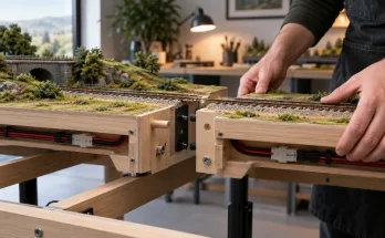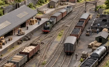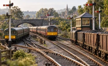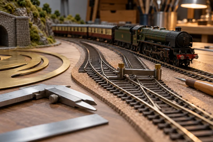
Ever spent hours building a beautiful model railway layout, only to watch your favourite locomotive derail at the same corner every single time?
It’s frustrating, especially when everything looks perfectly fine from a distance.
The problem often isn’t the locomotive itself. It’s the track geometry hiding underneath the scenery, platforms, bridges, and carefully arranged railway buildings.
When it comes to British railway modelling, reliable track design is about much more than connecting straight and curved sections. Every radius, turnout, gradient, and rail joint influences how smoothly your trains operate.
That’s why optimizing track geometry for reliable British railway models should be one of your priorities before installing permanent scenery.
Whether you’re recreating a Victorian branch line, a busy British Railways junction, or a modern passenger network, the principles of track alignment remain incredibly important.
A well-designed layout allows locomotives to negotiate curves naturally, keeps rolling stock stable, and reduces frustrating maintenance problems.
In this guide, we’ll explore practical track planning techniques, essential measurements, common design mistakes, and proven methods for achieving smoother, more realistic railway operations.
1. Understanding Track Geometry in British Model Railways
Track geometry describes the physical arrangement of railway lines, including curves, straight sections, turnouts, gradients, and the transitions connecting them.
On a full-sized railway, engineers carefully calculate these relationships to ensure trains can travel safely and efficiently.
Model railways follow many of the same principles, although the smaller dimensions create unique challenges.
A curve that appears reasonably gentle on a drawing can become surprisingly tight when a long passenger coach attempts to negotiate it.
Likewise, a small change in track height can cause a steam locomotive’s driving wheels to lose reliable contact with the rails.
Why Geometry Matters More Than Appearance
Imagine building an OO gauge station with a perfectly detailed platform, realistic signalling, and beautiful countryside scenery.
Everything looks fantastic until a six-coupled locomotive reaches a poorly aligned turnout.
The engine hesitates, the leading wheels lift slightly, and the train eventually derails.
This isn’t necessarily an electrical problem.
It may be caused by incorrect rail spacing, uneven vertical alignment, or a sudden change in curvature.
Reliable trackwork must accommodate the mechanical behaviour of locomotives and rolling stock.
Long-wheelbase steam engines, bogie coaches, and short freight wagons react differently to the same track arrangement.
A practical approach is to design around the most demanding vehicles you intend to operate, rather than assuming every model will behave identically.
2. Choosing the Correct Track Gauge and Rail Profile
Before calculating curve radii or positioning turnouts, you need to choose the appropriate track standard.
British railway modelling uses several established combinations of scale, track gauge, and wheel standards.
Although these systems may represent the same full-sized railway, their technical requirements aren’t interchangeable.
OO, EM, and P4 Gauge Differences
OO gauge remains one of the most popular choices for British railway enthusiasts.
It uses approximately 1:76.2 scale models running on track with rails spaced 16.5 mm apart.
This arrangement offers excellent compatibility with widely available ready-to-run locomotives, rolling stock, and track components.
However, the rail spacing is narrower than a true 4 mm scale representation of British standard gauge.
EM gauge increases the model track gauge to 18.2 mm, producing a more realistic relationship between railway vehicles and the track beneath them.
P4 modelling goes further, using a nominal track gauge of 18.83 mm and more precise wheel and track standards.
The Scalefour Society provides detailed technical guidance for these finescale arrangements.
For beginners, OO gauge generally offers the easiest starting point.
Experienced enthusiasts seeking improved dimensional accuracy may prefer EM or P4, but should account for wheel conversion and more demanding track construction.
Understanding Code 75 and Code 100 Rail
Another important consideration involves rail height.
In model railway terminology, the word code describes rail height in thousandths of an inch.
Code 100 rail measures 0.100 inches, or approximately 2.54 mm high.
Code 75 is lower, measuring approximately 1.91 mm.
For historical British layouts, finer rail profiles can create a more convincing appearance, particularly on lightly used branch lines and goods sidings.
However, lower rail profiles may cause clearance problems with certain older wheelsets that have deep flanges.
Before mixing track types, test your rolling stock and use suitable transition joiners or carefully prepared connections to compensate for different rail heights.
3. Calculating the Best Curve Radius for Smooth Train Movement
Curves are among the most common causes of derailments on model railways.
Tight bends force wheels, bogies, couplings, and locomotive mechanisms into positions that may exceed their designed movement.
Understanding the relationship between curve radius and vehicle length is therefore essential.
Standard OO Gauge Curve Radii
Many British OO gauge track systems use familiar sectional curve dimensions.
| Curve Type | Approximate Radius | Centreline Diameter |
|---|---|---|
| First Radius | 371 mm | 742 mm |
| Second Radius | 438 mm | 876 mm |
| Third Radius | 505 mm | 1,010 mm |
| Fourth Radius | 572 mm | 1,144 mm |
These dimensions are commonly associated with Hornby and PECO Setrack geometry.
However, they aren’t universal measurements for every brand or track system.
The diameter represents the track centreline circle, not the complete baseboard width required.
Additional room is necessary for sleepers, vehicle overhang, scenic structures, and safe clearance from the layout edge.
Why Broader Curves Usually Work Better
A first-radius curve may fit comfortably into a compact layout, but not every locomotive is designed to negotiate it.
Long steam engines and modern bogie vehicles may require considerably more space.
Third- or fourth-radius curves often offer a more attractive appearance and greater operating flexibility, provided the rolling stock supports them.
For example, a layout featuring long passenger coaches may benefit from curves of 600 mm or more.
A large scenic railway with generous available space might use radii exceeding 900 mm.
These are practical planning choices, not universal minimum specifications.
Always check the manufacturer’s minimum-radius requirements and test your longest vehicles before fixing the track.
Balancing Space and Reliability
Suppose your railway room only allows a baseboard depth of 1.2 metres.
A fourth-radius OO gauge curve has a centreline diameter of approximately 1.144 metres.
Although the track centreline theoretically fits, the complete curve would leave insufficient room for normal edge clearance.
You would need a larger footprint, a tighter radius, or a different layout arrangement.
This simple example demonstrates why track measurments should be calculated before construction begins.
Sometimes, reducing the number of tracks or adopting a point-to-point design produces a more reliable railway than forcing a continuous loop into limited space.
4. Using Transition Curves to Improve Railway Realism
One of the most effective ways to improve track geometry is to avoid abrupt changes between straight and curved sections.
Full-sized railways frequently use transition curves to introduce curvature progressively.
Model railway builders can apply the same principle with flexible track.
What Is a Transition Curve?
A transition curve, sometimes called an easement, gradually changes the track from a straight alignment into a tighter bend.
Rather than suddenly entering a constant-radius curve, the train experiences a smoother change in direction.
This can reduce sudden lateral movements and help body-mounted couplings remain properly aligned.
The effect becomes particularly noticeable with long passenger coaches.
A realistic train should glide into a curve rather than appear to jerk sideways.
Creating Smooth Curves With Flexible Track
Begin by marking the intended track centreline on the baseboard.
Use a flexible strip of wood, card, or another suitable guide to create a naturally flowing alignment.
Start with a very gentle bend, gradually increasing the curvature until the required main radius is reached.
Avoid introducing sharp kinks where flexible track sections join.
Rail joints should ideally be positioned on straight sections or carefully aligned portions of the curve.
When the track follows a smooth continuous path, both appearance and operation generally improve.
For particularly demanding layouts, trial-fit several flexible track sections before securing them permanently.
This approach makes it easier to correct aligment problems without damaging expensive track components.
5. Designing Reliable Turnouts and Railway Junctions
Turnouts, commonly called points in British railway terminology, are another critical element of dependable track design.
They allow trains to move between tracks, enter sidings, and negotiate station approaches.
However, they also introduce additional mechanical complexity.
Moving switch blades, crossing noses, check rails, and changes in track direction must work together accurately.
Understanding Point Radius and Crossing Geometry
Commercial turnouts come in various lengths and geometries.
Compact points are useful where space is limited, particularly in small industrial yards.
Larger turnouts generally provide smoother routes for longer locomotives and passenger vehicles.
However, a turnout’s overall length doesn’t automatically tell you its minimum curvature.
Different manufacturers describe turnout geometry using terms such as short radius, medium radius, long radius, or numbered crossing angles.
Always examine the actual technical drawing before purchasing.
Avoiding Problems With Reverse Curves
An S-curve occurs when a curve in one direction leads directly into another bending the opposite way.
These formations can cause problems when adjacent vehicles experience opposing lateral forces.
Body-mounted couplings are particularly vulnerable.
The National Model Railroad Association recommends separating reverse curves with an adequate straight section.
A useful starting guideline is approximately 1.5 times the length of the longest vehicle, with additional space preferable where possible.
This isn’t a guarantee for every model, so physical testing remains essential.
When designing a station throat or crossover, avoid placing opposing points so close together that long vehicles must negotiate sudden changes in direction.
Checking Turnout Construction
Before permanently installing points, inspect the switch blades and crossing area.
The blades should close correctly against their stock rails, and wheelsets should pass through without climbing or binding.
Use a track gauge compatible with your modelling standard.
Also check the wheel back-to-back dimensions of any troublesome locomotives or wagons.
For live-frog turnouts, ensure the crossing polarity and any required rail insulation are correctly arranged.
Reliable electrical supply is especially important when short-wheelbase locomotives move slowly through complicated pointwork.
6. Planning Gradients and Vertical Track Transitions
Horizontal track geometry receives considerable attention, but vertical alignment can be equally important.
Model railways frequently use gradients to connect different elevations, cross bridges, or create scenic depth.
Poorly designed changes in height can cause wheel lifting, unwanted uncoupling, and reduced locomotive traction.
Understanding Gradient Percentages
Railway gradients can be expressed as percentages.
A 2% gradient means the track rises 20 mm for every metre of horizontal distance.
Similarly, a 3% gradient rises 30 mm per metre.
These figures can look modest on paper, but their impact on locomotive performance may be significant.
For example, climbing 100 mm at a constant 2% gradient requires approximately five metres of horizontal distance.
This calculation doesn’t include additional space for vertical transitions.
The distance becomes even more demanding when bridges, tunnels, and supporting structures must fit into the layout.
Why Vertical Transitions Matter
A sudden change from level track to an incline can cause problems for rigid-wheelbase steam locomotives.
At the beginning of the gradient, some wheels may temporarily lose contact with the rails.
The same problem can occur where the track returns to a level section.
Instead of using abrupt changes, introduce smooth vertical transitions.
Flexible roadbed supports and accurately shaped substructures can help establish the required profile.
Avoid placing turnouts directly across abrupt gradient changes.
Pointwork operates most reliably when it sits on a stable, accurately formed surface.
Testing Locomotive Hauling Capacity
Not every locomotive handles gradients equally well.
Traction depends on locomotive weight, driven wheels, available adhesion, train length, and the resistance of rolling stock.
Before building a permanent incline, create a temporary test section.
Run your intended locomotives with realistic train loads and observe their performance.
If a locomotive struggles, consider reducing the gradient, shortening the train, or changing the route design.
7. Maintaining Accurate Track Spacing and Clearances
Another common problem involves positioning parallel railway lines too close together.
Two trains may pass without difficulty on straight tracks but collide when entering adjacent curves.
This occurs because railway vehicles don’t follow the track centreline with their entire bodies.
Understanding Vehicle Overhang
Long bogie coaches behave differently from short freight wagons.
On curves, the middle of a vehicle can project toward the inside of the bend, while its ends may swing outward.
The amount of movement depends on the vehicle’s dimensions, bogie spacing, and curve radius.
This becomes especially important around curved platforms, tunnels, bridges, and double-track sections.
Testing Real-World Clearances
A practical technique is to place your longest passenger coach on the proposed curve before securing the tracks.
Move it slowly through the entire section while checking nearby vehicles and structures.
Repeat the process on the neighbouring track with another large vehicle.
Don’t rely entirely on nominal track spacing.
Actual clearances can differ depending on the models being operated.
Also remember that overhang affects platform edges and tunnel entrances.
A platform positioned perfectly alongside straight track may be too close to a coach negotiating a curved station approach.
Leave enough clearance for movement while maintaining a visually realistic appearance.
8. Installing Flexible Track and Preventing Common Problems
Even a well-designed track plan can fail if the physical installation is poor.
Baseboard stability, rail joints, track fastening, and electrical connections all influence railway performance.
A small construction error can become difficult to repair once ballast and scenery are installed.
Preparing the Baseboard and Trackbed
Start with a stable baseboard that resists unwanted movement and twisting.
The surface supporting the track should be smooth, clean, and properly levelled where required.
Cork or another suitable underlay can help create a consistent trackbed.
However, underlay won’t correct major structural defects.
Check the surface with a straightedge before laying the rails.
Any unwanted bumps or depressions should be corrected before track installation begins.
Securing Track Without Distortion
Flexible track should follow its intended curve naturally.
Avoid forcing it into position with excessive pressure.
Track pins driven too deeply can distort sleepers and alter rail spacing.
Adhesive fixing methods are another option, particularly where carefully controlled positioning is important.
Whichever method you choose, maintain consistant rail alignment throughout installation.
At rail joints, remove burrs and check that the rail ends meet smoothly.
Where rail sections differ in height, use suitable transitions rather than forcing mismatched rail heads together.
Electrical Reliability and Rail Connections
Poor electrical continuity can imitate mechanical track problems.
A locomotive that suddenly stops on a turnout may have encountered a dead section rather than defective geometry.
Use reliable track feeders, particularly on larger layouts or installations using Digital Command Control.
Don’t depend exclusively on rail joiners to carry power across an extensive railway network.
For complex pointwork, follow the manufacturer’s wiring instructions and verify electrical polarity before operating trains.
Good track geometry and dependable electrical installation should be treated as complementary requirements.
9. Testing Track Geometry Before Adding Scenery
Perhaps the most important stage of railway construction happens before the final scenery is installed.
Testing allows you to identify weak points while adjustments are still relatively easy.
Once buildings, ballast, platforms, and landscape materials are permanently attached, correcting track geometry can become considerably more complicated.
Creating a Practical Testing Routine
Begin with a small locomotive that runs reliably at low speeds.
Operate it in both directions through every curve, turnout, and siding.
Next, test a long-wheelbase steam locomotive or another vehicle known to be sensitive to uneven trackwork.
Finally, run your longest passenger coaches and realistic freight formations.
Observe their behaviour during acceleration, braking, and slow-speed shunting.
Pay particular attention to reverse curves, curved crossings, and changes in gradient.
A route that works at moderate speed may reveal problems when trains move slowly.
Testing Under Realistic Operating Conditions
Don’t limit testing to individual locomotives.
Run complete trains with the loads you expect to use during normal operating sessions.
A locomotive pulling one coach may negotiate a tight curve successfully but struggle when hauling a longer train.
Also test propelling movements.
Wagons being pushed through a turnout can behave differently from the same vehicles being pulled.
For exhibition layouts, repeat tests after moving or assembling the baseboards.
Transport and temperature changes can sometimes affect track joints and board alignment.
Establishing a Maintenance Routine
Reliable operation requires occasional inspection even after construction is complete.
Check rail cleanliness, point movement, electrical connections, and any joints that begin to show signs of deterioration.
Keep the running surfaces clean using appropriate methods that won’t damage the track.
Inspect wheelsets for accumulated dirt and confirm that couplings operate freely.
Regular maintanance helps prevent small problems from developing into persistent derailments or electrical failures.
10. Combining Operational Reliability With Authentic British Railway Design
The best British model railway layouts don’t simply function well.
They also capture the appearance and operating character of real railway infrastructure.
This requires balancing practical modelling limitations with historical accuracy.
Studying Real British Railway Track Arrangements
Historic railway maps, station diagrams, and photographs can reveal how railway engineers arranged tracks around stations, junctions, and goods yards.
Rural branch lines often had relatively simple infrastructure.
Major junctions, by comparison, required more extensive pointwork, crossovers, and multiple running lines.
Avoid adding complicated track arrangements simply because they fill available space.
Every siding and crossover should serve a believable operational purpose.
For a small branch-line station, a passenger platform, run-round loop, and goods siding may provide enough variety for engaging operating sessions.
Using Selective Compression Carefully
Selective compression involves reducing prototype distances to fit a model into limited space.
It’s a useful technique, but excessive compression can create unrealistic curves and poorly positioned turnouts.
Try shortening long straight sections before tightening curves beyond the capabilities of your locomotives.
Preserve essential relationships between platforms, points, signal boxes, and goods facilities.
If a realistic arrangement simply won’t fit, consider modelling a smaller station or a different section of railway.
A compact layout with generous curves and dependable operations is usually more satisfying than an overcrowded design that constantly causes problems.
Optimizing track geometry for reliable British railway models is one of the most valuable investments you can make in your railway modelling hobby.
Smooth curves, correctly positioned turnouts, manageable gradients, accurate track spacing, and carefully installed rail joints all contribute to dependable operations.
The secret isn’t building the most complicated track network. It’s creating a layout where every component works together naturally.
Whether you’re working with OO gauge, EM, or P4, thoughtful planning and thorough testing can prevent countless problems later.
Start with your largest locomotives and longest coaches, establish suitable track dimensions, and test the complete arrangement before installing permanent scenery.
Ready to improve your railway layout? Review your track plan, identify potential trouble spots, and start refining your railway geometry for smoother, more enjoyable operations.