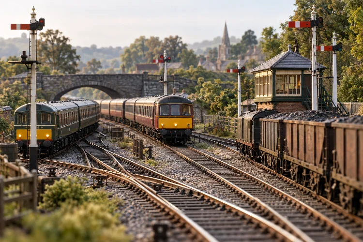
Imagine operating a model railway where two passenger trains approach the same junction, a freight service waits for clearance, and a branch-line locomotive prepares to join the main line.
Suddenly, the railway becomes more than a collection of miniature tracks and moving trains.
Every signal matters. Every turnout has a purpose. And every train movement needs careful coordination.
That’s the real appeal of designing operationally realistic model railway junction layouts.
Instead of building complicated track arrangements simply because they look impressive, you’re recreating the decisions, restrictions, and working practices found on actual railway networks.
A successful junction layout combines accurate track geometry, realistic signalling, reliable electrical systems, and believable train schedules.
It also needs to be enjoyable to operate, whether you’re controlling everything yourself or working with several railway enthusiasts.
The good news? You don’t need an enormous layout or sophisticated automation to achieve convincing results.
With the right planning techniques, even a relatively compact OO or N gauge railway can reproduce the operational challenges of a busy British junction.
Let’s explore how to make every train movement feel like part of a real working railway.
1. Understanding How Real Railway Junctions Operate
Before drawing a track plan, it’s important to understand what makes railway junctions different from ordinary stations or continuous-running layouts.
A junction connects two or more railway routes, allowing trains to change direction, join another line, or continue toward different destinations.
That sounds straightforward, but the operational possibilities quickly become interesting.
Why Junctions Create Operational Challenges
Imagine a double-track main line with a single-track branch joining from one side.
An express passenger train approaches on the main line, while a local passenger service waits on the branch.
Both trains cannot necessarily occupy the junction simultaneously because their routes may conflict.
The signal operator must establish a safe route, confirm the points are correctly positioned, and authorise the appropriate movement.
In a model railway, reproducing these decisions adds an entirely new dimension to train operation.
Instead of allowing trains to move randomly, you’re managing traffic across a miniature transport network.
Study Real Junction Arrangements
British railway history provides excellent inspiration for junction modelling.
Traditional junctions ranged from relatively simple branch-line connections to complicated railway intersections serving industrial districts and major cities.
Some included dedicated goods loops, avoiding lines, or extensive sidings.
Others consisted of little more than a carefully signalled connection between two routes.
Study historical track diagrams before planning your layout.
Understanding why a particular crossover or siding existed is much more useful than copying an arrangement simply because it looks impressive.
2. Choosing the Right Junction Type for Your Layout
Not every railway junction needs a complex track arrangement.
The best design depends on your available space, historical setting, and preferred operating style.
Simple Branch-Line Junctions
A basic branch-line junction connects a secondary route with a larger railway.
For a compact British layout, this might represent a rural branch connecting to a double-track main line.
The main line carries regular passenger and freight services, while occasional local trains enter or leave the branch.
This arrangement provides meaningful operational variety without requiring dozens of turnouts.
It also allows the modeller to create realistic waiting periods when branch services must give way to main-line traffic.
Double Junctions and More Complex Connections
A double junction can provide connections between two double-track routes.
Depending on the prototype, the arrangement may involve multiple turnouts, crossovers, and potentially diamond crossings.
These features create opportunities for more complicated train routing.
However, they also consume valuable space and increase maintenance requirements.
A complicated junction isn’t automatically better than a simple one.
The goal should be to recreate an appropriate pattern of railway traffic rather than install as much track as possible.
Select a Historical Period
The junction’s signalling and traffic should match the era being modelled.
A 1930s British railway might feature semaphore signals, mechanical signal boxes, and steam locomotives.
A later British Railways layout could include diesel traction, colour-light signalling, and more modern point-control equipment.
Selecting a consistent historical period helps prevent unrealistic combinations of infrastructure and rolling stock.
3. Planning Track Geometry for Reliable Train Movements
Track geometry is one of the most important parts of operational railway design.
Poorly arranged curves and turnouts can create derailments, unreliable coupling, and unrealistic locomotive movements.
Even an attractive track plan can become frustrating when trains struggle to navigate the junction.
Turnout Selection and Placement
Turnouts allow trains to move between routes.
They must be selected according to the intended operating speed, available space, and type of rolling stock.
On model railways, manufacturers often provide different turnout geometries, including compact, medium, and larger-radius designs.
Larger, gentler turnouts generally provide smoother-looking movements and can be more suitable for longer vehicles.
Compact points save space but may introduce sharper directional changes.
Avoid arranging consecutive turnouts without considering the resulting track alignment.
Abrupt reverse curves, often called S-curves, can cause particular problems with long coaches and vehicles fitted with close couplings.
Where practical, use gentler transitions or short straight sections between opposing curves.
Understanding Minimum Radius
There isn’t one perfect minimum radius for every model railway.
It depends on the scale, locomotive wheelbase, coach length, coupling design, and manufacturer’s recommendations.
A small branch-line tank engine may negotiate curves that would be unsuitable for a large express locomotive.
For OO gauge layouts, generous main-line curves are especially valuable when operating long passenger coaches.
Don’t assume that a locomotive successfully negotiating a curve means it will perform equally well through a turnout combination.
Test complete train formations, including their couplings and overhang, before finalising the track.
Calculating Useful Loop Lengths
Passing loops and holding sidings must accommodate the trains intended to use them.
For example, suppose your longest model train measures 105 centimetres.
A passing loop with 120 centimetres of usable length between its clearance points would provide 15 centimetres of total spare capacity.
This is only an illustrative starting point, not a universal engineering standard.
Actual capacity depends on signal positions, turnout geometry, fouling points, and the stopping space required.
Remember that the physical length of a siding isn’t necessarily its usable length.
A beautifully constructed loop becomes ineffective if a stopped train blocks an adjoining route.
4. Designing Junctions Around Operational Traffic Flow
An effective model railway junction starts with train movements rather than scenery.
Ask yourself which trains will use the junction, where they originate, and what conflicts might occur.
The answers determine which tracks and signalling arrangements are actually necessary.
Establish Train Priorities
Real railway operations often involve different service categories.
An express passenger train might receive priority over a slower freight movement, depending on the timetable and operating circumstances.
At a model junction, this creates realistic decisions.
A goods train might wait in a loop while a passenger service passes.
Alternatively, a branch train could remain at its protecting signal until the main-line route becomes available.
These interactions make railway operation feel purposeful.
Identify Conflicting Routes
Two train movements conflict when they require track sections that cannot safely be occupied simultaneously.
Consider a branch train crossing the opposing main line to reach its destination.
That movement may temporarily prevent other trains from using the crossing route.
The track plan should make these conflicts clear.
It’s helpful to sketch the junction as a simplified diagram and trace every possible train movement.
Identify where trains can wait without blocking other routes.
A well-designed junction offers useful operational choices without generating unnecessary congestion.
Include Realistic Holding Locations
Holding loops, platform roads, and suitable approach sections provide places for trains to wait.
However, adding them should reflect the prototype being modelled.
A quiet rural junction may not justify extensive storage tracks, while a busy freight connection might require dedicated holding facilities.
Think carefully about how each additional track improves operations.
A single well-positioned loop can sometimes offer more value than several poorly arranged sidings.
5. Recreating Authentic Railway Signalling and Interlocking
Signalling is what turns a group of connected tracks into a controlled railway junction.
Without realistic signalling procedures, operators can unintentionally establish conflicting routes.
A believable signalling system provides structure and prevents those movements.
Semaphore Signals on Historic Layouts
Semaphore signals are particularly attractive for British steam-era modelling.
Traditional junction signals often used multiple arms to communicate which route had been established.
The exact arrangements varied between railway companies and periods.
A signal protecting a junction might control movements toward the main route and a diverging branch.
In historically accurate signalling, the signal position, point setting, and route conditions must correspond.
Study genuine signalling diagrams wherever possible.
Understanding Route Interlocking
Interlocking prevents incompatible routes from being established simultaneously.
For instance, a signal should not clear for a train to take the branch while the junction points are set for an conflicting movement.
A model railway can reproduce this principle mechanically, electrically, or through software.
The controls should require the correct route to be established before the relevant signal can show a proceed indication.
Route interlocking doesn’t necessarily require a complicated computer system.
A carefully designed control panel with appropriate electrical logic can provide a convincing representation.
Keep Signalling Consistent With the Era
Modern colour-light signals and traditional mechanical semaphore systems have different operating characteristics.
Avoid combining equipment without a historical or operational justification.
For a 1950s junction, research whether the chosen railway location used mechanical signalling or had already undergone modernisation.
For modern layouts, route indicators and train detection systems may be more relevant.
Accurate signalling makes the operating experience far more immersive.
6. Integrating Passing Loops, Sidings, and Freight Connections
Railway junctions often developed because particular locations needed connections between passenger routes, goods facilities, and industrial destinations.
These supporting features can create plenty of operational interest.
However, they should be positioned carefully.
Designing Functional Passing Loops
On a single-track route, a passing loop allows opposing trains to cross at a designated location.
The loop must be long enough for the intended trains, and its signalling arrangement must support the planned movements.
At a branch junction, a loop might also allow a goods train to wait while another service passes, depending on the track layout.
Consider whether a train occupying the loop would obstruct the junction points.
This is an easy problem to overlook during the planning stage.
Adding Freight and Industrial Traffic
A junction serving an industrial area might include sidings for coal, agricultural products, machinery, or general merchandise.
These tracks create opportunities for shunting and wagon exchange.
Imagine a local goods train arriving with four wagons for different customers.
The locomotive must seperate the wagons, position them appropriately, and collect outgoing vehicles.
Meanwhile, the main-line operator must decide when freight movements can safely cross the junction.
The result is a much more engaging railway than one where trains simply circulate continuously.
Don’t Overcrowd the Junction
Every extra siding introduces another turnout, electrical connection, and potential maintenance issue.
More importantly, it changes the operational character of the railway.
A small country junction with an enormous marshalling yard might look unrealistic unless the location has a clear historical explanation.
Prioritise tracks that contribute directly to your operating plan.
7. Selecting Reliable Control and Electrical Systems
Even the most carefully researched junction won’t be enjoyable if its electrical system is unreliable.
Multiple turnouts and crossing routes make good wiring particularly important.
Fortunately, both traditional analogue control and Digital Command Control (DCC) can support convincing railway operations.
Analogue Versus DCC Operation
Analogue control uses electrical sections to regulate locomotive movement.
With suitable wiring and switches, operators can control different parts of a junction independently.
DCC allows individual locomotives to respond to commands through the track’s digital control signal.
This can make operating multiple locomotives on shared electrical sections more flexible.
However, DCC does not automatically provide route protection, train detection, or realistic signalling.
Those features require additional design and equipment.
Point Motors and Route Control
Electric point motors and servo mechanisms make remote turnout operation possible.
Servos are particularly useful because their movement speed and end positions can be adjusted with suitable controllers.
This allows model points and semaphore signals to move more gradually.
Some layouts use route-setting panels, where an operator selects a destination and the required points move into position.
For a junction with numerous turnouts, this can simplify operations considerably.
Nevertheless, manual point control remains perfectly suitable for smaller layouts.
Plan for Maintenance Access
Electrical reliability depends on more than selecting the right controller.
Turnout frogs, rail joiners, power feeds, and insulated sections need careful attention.
Provide dependable connections and test every route under realistic operating conditions.
Avoid installing complicated point mechanisms beneath permanently inaccessible scenery.
Future maintenence is much easier when motors, wiring, and control modules remain accessible.
8. Creating Realistic Timetables and Operating Sessions
Once the track and signalling systems are complete, a timetable can transform the layout into a functioning railway.
Rather than running whichever train happens to be nearby, operators follow a planned sequence of services.
This introduces train priorities, waiting periods, and realistic traffic interactions.
Develop a Working Timetable
Start by identifying the different types of trains operating through the junction.
These might include main-line passenger services, branch passenger trains, goods workings, and occasional light-engine movements.
A fictional timetable could begin with a passenger express passing through the main line.
A local service then arrives from the branch, followed by a freight working requiring access to a nearby siding.
Each train has a specific origin, destination, and operational purpose.
The schedule should allow realistic time for point changes, train movements, and shunting.
Introduce Sequence-Based Operations
A strict clock-based timetable isn’t always practical on a compact model railway.
An alternative is a sequence timetable.
Instead of requiring a train to depart at an exact simulated time, movements happen in a predetermined order.
For example, the branch passenger train may depart once the main-line express clears the junction.
The goods service can then proceed after the branch connection becomes available.
This approach retains operational structure without putting excessive pressure on the operator.
Use Small Operational Variations
Real railways experience delays, changing traffic patterns, and occasional additional services.
Introducing similar variations can make model railway sessions more interesting.
A late-running passenger train might delay a goods movement, or an extra wagon collection might extend a shunting operation.
Use these disruptions occassionally rather than introducing constant chaos.
The challenge should feel realistic and enjoyable, not unnecessarily frustrating.
9. Example: Designing a Fictional British Junction Layout
Let’s bring these principles together with a practical example.
Imagine a fictional railway location called Westford Junction, set in the British Railways Eastern Region during 1958.
The junction connects a double-track main line with a single-track rural branch.
A small goods facility provides local freight traffic, while a signal box controls the principal movements.
Creating the Track Plan
Assume the available modelling area is approximately 3.6 metres long and 0.6 metres deep, with additional off-scene storage where space permits.
The main line runs across the visible section, with the branch diverging toward a hidden fiddle yard.
Appropriate pointwork provides the connection between routes.
A short goods siding serves a nearby agricultural merchant, while the signalling arrangement protects movements between the branch and main line.
The dimensions are illustrative, and the actual design would need testing against turnout templates and train lengths.
If the branch requires a second connecting crossover or a holding loop, those elements must be justified by the intended movements.
Planning the Operating Session
The session begins with a main-line passenger train passing through the junction.
A branch passenger service waits until the required main-line route becomes clear.
Once permission is available, the signal operator establishes the branch route and allows the local train to proceed.
Later, a goods train arrives with wagons intended for the agricultural merchant.
The locomotive must reach the appropriate siding without interfering with other scheduled movements.
After the freight work is completed, the goods train prepares to leave.
The operator then restores the relevant points and signals for normal main-line running.
This small sequence creates meaningful interaction between passenger services, freight operations, and junction control.
Expanding Operational Variety
You could introduce an additional passenger service or occasional special freight movement.
Another possibility is a temporary engineering restriction affecting one route.
For exhibition layouts, two operators can divide responsibilities between locomotive driving and signal-box control.
That arrangement creates a stronger impression of a genuine railway operation.
Even without adding more track, the same layout can support different sessions simply by changing train schedules and wagon assignments.
10. Testing and Improving Junction Layout Performance
A successful railway junction should be thoroughly tested before scenery is permanently installed.
Temporary track arrangements are extremely useful during the planning stage.
They allow you to identify unreliable curves, awkward turnout positions, and insufficient siding lengths.
Test Complete Train Movements
Don’t test only individual locomotives.
Run complete passenger and freight trains through every intended route.
Check movements at low speeds, particularly where vehicles pass through multiple turnouts.
Confirm that trains can stop clear of adjacent lines and that couplings behave reliably.
If certain movements regularly cause problems, adjust the geometry rather than accepting frequent derailments.
Simulate an Entire Operating Session
Before completing the landscape, operate the junction according to its proposed timetable.
You may discover that a holding loop is too short or that a goods siding requires an inconvenient movement across the main line.
These discoveries are much easier to address before the track becomes permanent.
Keep a short record of operating problems and potential improvements.
With each session, refine the layout until train movements become smooth and predictable.
Remember that operational realism comes from dependable infrastructure and believable procedures, not from unnecessary complexity.
Designing operationally realistic model railway junction layouts is about creating a miniature railway where every track, signal, and train movement serves a genuine purpose.
The most successful designs begin with a clear understanding of railway operations, followed by thoughtful track geometry, suitable signalling, and reliable control systems.
Realistic timetables, freight connections, and well-positioned passing loops can make even a small layout feel surprisingly sophisticated.
You don’t need to recreate a massive railway interchange to enjoy these benefits.
Start with a simple junction, identify the movements it needs to support, and test the design before permanently installing the track.
As your confidence grows, introduce more advanced signalling and operational challenges.
The next time a train approaches your model junction, make sure its journey involves more than simply turning a point.
Make every movement count.